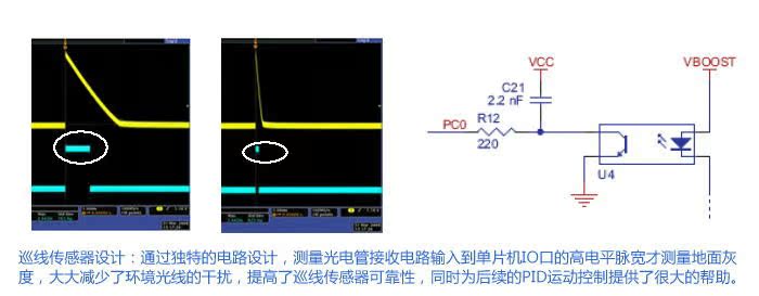
本产品为美国Pololu公司的原版产品,配套资料均为英文,对用户英语有较高要求,您一定要确定没有问题再选择购买,“中国机器人超市”不承诺提供对应的中文资料哦。

Pololu公司生产的3Pi(3π)是一款可以完成巡线和走迷宫功能的轮式机器人。该产品具有体积小巧、转速高、功能强大、用料上乘、设计美观等优点。采用ATmega328P(旧款使用ATmega168)控制器,支持C/C++编程,同时支持时下非常流行的Arduino系统。用户在使用该款产品时,不但能学习ATmega系列单片机的支持以及C/C++编程,更可以学习机器人运动控制算法(如PID算法)以及迷宫最优路径找寻算法。从硬件和软件两个方面提高用户的能力。
3Pi智能车提供了非常丰富的资料,如非常详细的用户手册、丰富的函数库、配套的源程序、电路原理图以及迷宫制作方法和算法等等。

直径:9.5cm
重量:83g(不含电池和编程器)
速度:100cm/秒(使用4AAA电池情况下)
处理器: ATmega168/328P
电机驱动: TB6612FNG
电机数量: 2
使用I/O: 21
最小工作电压: 3.2V
最大工作电压: 7.2V
PWM最大频率: 80 kHz

1.描述Description:
"...the 3pi has been more thoroughly field tested than any other robot we’ve worked with. We’ve had way too much fun with this little robot and by the time you finish reading the review, you’ll probably want to buy one or two for yourself."
R. Steven Rainwater, robots.net.
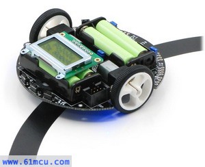
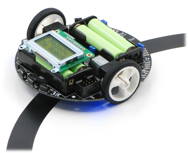
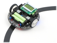
The 3pi robot is designed to excel in line-following and maze-solving competitions. It has a small size (9.5 cm/3.7" diameter, 83 g/2.9 oz without batteries) and takes just four AAA cells (not included), while a unique power system runs the motors at a constant 9.25 V independent of the battery charge level. The regulated voltage allows the 3pi to reach speeds up to 100 cm/second while making precise turns and spins that don’t vary with the battery voltage.
The 3pi robot makes a great platform for people with C programming experience to learn robotics, and it is a fun environment for ambitious beginners to learn C programming. At its heart is an Atmel ATmega328P microcontroller running at 20 MHz and featuring 32 KB of flash program memory, 2 KB RAM, and 1 KB of persistent EEPROM memory. The popular, free GNU C/C++ compiler works perfectly with the 3pi, Atmel’s AVR Studio provides a comfortable development environment, and an extensive set of libraries provided by Pololu makes it a breeze to interface with all of the integrated hardware. The 3pi is also compatible with the popular Arduino development platform. We provide a number of sample programs to show how to use the various 3pi components, as well as how to perform more complex behaviors such as line following and maze solving.
2、规格Specifications:
Processor: ATmega168/328P
Motor driver: TB6612FNG
Motor channels: 2
User I/O lines: 21
Minimum operating voltage: 3 V2
Maximum operating voltage: 7 V2
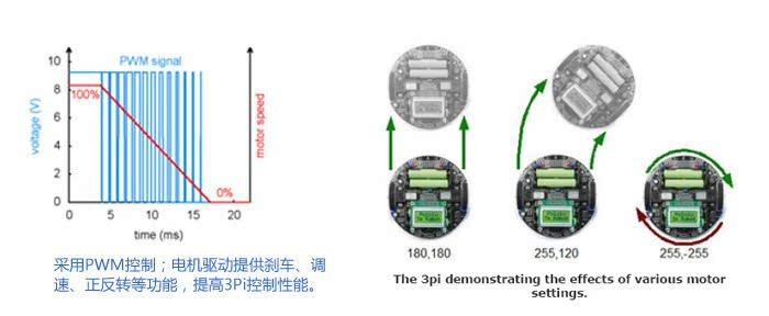
Maximum PWM frequency: 80 kHz
Reverse voltage protection?: Y
External programmer required?: Y
3、图片Pictures:
|
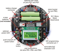
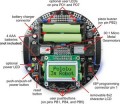
General features of the Pololu 3pi robot, top view.
|
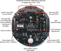
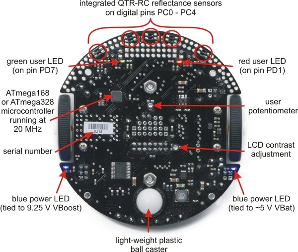
Labeled bottom view of the Pololu 3pi robot.
|
|
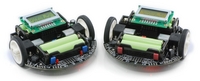
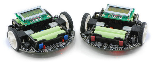
Pololu 3pi robots.
|
Pololu 3pi robot on a 3/4" black line.
|
|

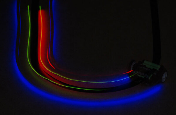
A 3pi robot following a line in the dark, making the glow of the LEDs more apparent.
|
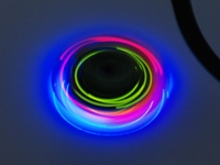
A 3pi robot spinning in place in the dark after losing the line.
|
4、资源Resources:
5、常见问题FAQs:
- How do you pronounce “3pi”, anyway?
-
The “pi” in 3pi is pronounced like the greek letter π (e.g. three-pie). The name comes from the size of the robot’s chassis, which is approximately 3pi centimeters (9.4 cm, 3.7"in) in diameter.
-
- How does the battery charger connection work? Is there a charger included?
-
The 3pi robot does not include batteries or a charger. The battery charger connection provides a direct connection to the batteries so that if you use rechargeable batteries, you can recharge them without taking them out of the robot. You will need a charger capable of charging four NiMH or NiCD cells (depending on what you’re using) in series. Such chargers are readily available in hobby stores for charging electric model airplane battery packs. Please note that rechargeable batteries are not required as the 3pi can use regular alkaline cells, but we strongly recommend investing in some NiMH cells and a charger.
-
- I’m ready to order a 3pi, but am wondering what sort of battery charger I need. Any recommendations?
-
You will only need a battery charger if you plan on powering your 3pi with rechargeable cells. The features you want are ability to charge 4 NiMH cells in series (they are usually in battery packs, not in battery holders like on the 3pi) and to be powered by AC (a wall outlet). In general, having more flexibility (such as the ability to charge 1-8 cells) is nice for future projects. Though we don’t have experience with these particular models, the following chargers look like they should be nice:
Tower Hobbies AC/DC Digital Peak Charger w/LCD
Triton Jr (customer-recommended)
These chargers can be connected directly to the 3pi’s battery charge port, allowing you to charge the batteries while they are still in the robot.
Since the 3pi just uses ordinary AAA batteries, you can buy battery chargers (into which you stick the batteries) at most general electronics stores. For example, a quick search of the Radio Shack web site yields:
4-6 Hr. Battery Charger + 4 AA & 4 AAA Ni-MH Batteries
The downside to a charger like this is that you have to remove the batteries from the 3pi to charge them.
-
- The green (PD7) user LED on my 3pi flickers even though I’m not doing anything with it. Is it malfunctioning?
-
No, this behavior is normal. To get the most out of the ATmega168’s I/O lines, one of the LCD’s data lines (PD7) doubles as the control line for the green LED, so this LED might flicker when the LCD is updated. As such, the amount of flickering and effective brightness of the LED will generally be a function of the rate at which you are updating the LCD. Note that you can change the state of the green LED without affecting the LCD at all, and using the LCD via the Pololu AVR library will only very briefly change the state of the LED line as needed before restoring it to its previous state.
-
- Can I augment/customize my 3pi by adding my own electronics/sensors?
-
Yes. The easiest way to augment your 3pi is through an expansion kit, which can comes either with cutouts that let you see the LCD below or without cutouts. The version without cutouts replaces the LCD, giving you access to more I/O lines and more prototyping space. An expansion kit is not required for addition of your own electronics, however.
The 3pi robot has a limited number of free I/O lines that can be used as inputs for additional sensors or to control additional electronics such as LEDs or servos. Please see section 10.c of the 3pi user’s guide for more information.
- Are wheel encoders included or can they be added to the 3pi robot? Are there sufficient I/O lines available for encoders?
-
Unfortunately, there is no provision for encoders on the 3pi: we do not have any sensor solution and the microcontroller does not have enough I/O lines. Therefore, the only way to add encoding is to make your own sensor setup and to use an external microcontroller (for example, on an expansion PCB) to do the sensor reading. The secondary microcontroller can communicate with the main 3pi controller using the asynchronous serial lines, which are available for expansion purposes.
-
- I’m adding peripherals to the 3pi that require 5 V. How much current can the 5 V (Vcc) power bus supply?
-
Because the 5 V goes through two power stages, the answer is not completely clear-cut. The 5 V regulator itself has a 900 mW power dissipation limit, so with a 4.3 V drop from the 9.3 V boost voltage to 5 V, we get just over 200 mA. The stock electronics on the 3pi typically use under 50 mA (however, this depends on what your program is doing, if you are making high-frequency noise with the buzzer, and so on), so you could figure an absolute max of 150 mA, with 100 mA being a more comfortable guideline.
However, the boost voltage has a limit of its own of around 1 A, which is dependent on your battery voltage. The motors and IR LEDs also use this supply, so using a lot for your 5 V will affect what is available for the motors. You can almost stall the motors and still have the full boost voltage on the motors in the stock configuration; if you’re also drawing an extra 200 mA for other electronics, the boost voltage will start dropping as the motors approach stall, though this is not necessarily a bad thing since it will limit the stress on the motors and lower the voltage drop on the linear regulator.
-
- What is the purpose of the small piece of electrical tape stuck on the bottom of the 3pi PCB near the ball caster? Can I remove it?
-
The electrical tape provides extra protection for the boost regulator circuit. It is easy to touch this area of the PCB with your finger when pushing the power or reset button, and without the tape your finger can change the boost voltage to levels that are out of spec for components on the board. We do not recommend that you remove it.
|
6、备注Notes:
6.1 Digital I/O lines PD0 and PD1 are available; two more analog inputs and one analog/digital pin can be made available by removing jumpers and disabling special features of the board.
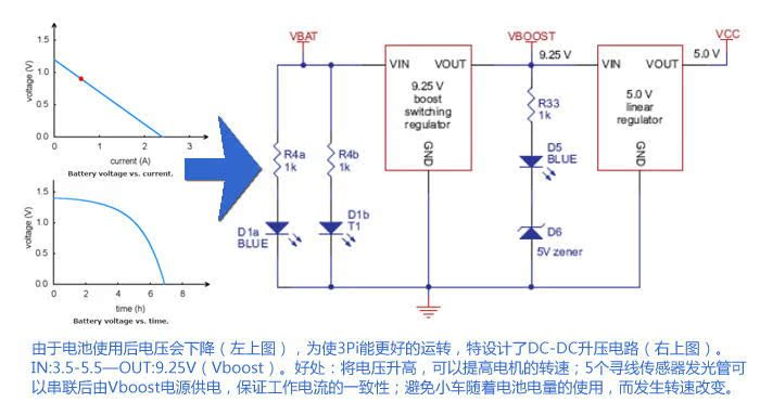
6.2 Designed for use with 4 x AAA NiMH or Alkaline cells. A step-up regulator boosts the motor voltage to 9.25 V.